The Biomechanics of KD & TF Prostheses

An interactive review: flip the cards, move the sliders, then test yourself.

SIPO 347 & 348 · Lecture Tue 29 Sep 2026
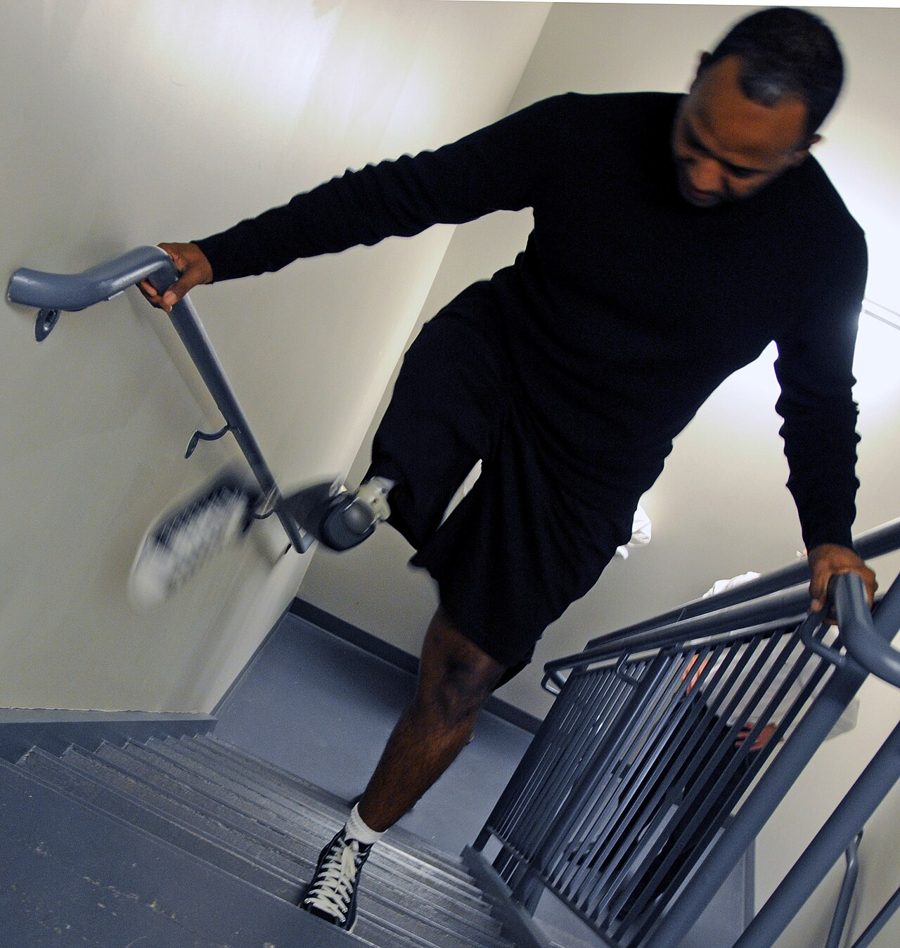
Photo: Axiles Bionics, Wikimedia Commons, CC BY-SA 2.0
A man with a lower-limb prosthesis climbing stairs using the handrail
Start here

How to use this page

The page follows the five sections of the lecture. Each section has real images, then something to try. Finish with the self-check quiz.

This review does not count towards your grade. The graded post-quiz is on Canvas.

Begin review

Photo: The U.S. Army, Wikimedia Commons, public domain
Sections 1–2

Deficits & weight-bearing

Section 3

Pelvic stability

Section 4

Knee stability

Section 5

Swing phase

Sections 1–2

Deficits & weight-bearing

What each amputation level keeps or loses, and how the socket takes load.

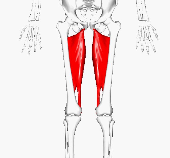
3D render of both adductor magnus muscles, highlighted in red, running from the pelvis down the inner thigh
The adductor magnus inserts low on the femur. KD keeps this insertion; most TF amputations lose it, so the femur drifts into abduction. Image: BodyParts3D/Anatomography, “Adductor magnus”, Wikimedia Commons, CC BY-SA 2.1 JP. Single frame, cropped.
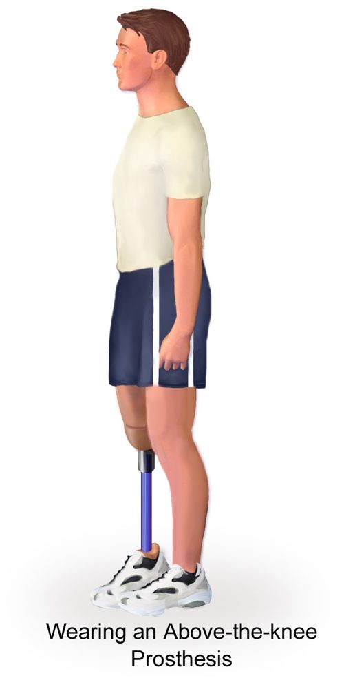
Illustration of a person standing side-on wearing an above-knee prosthesis
A TF socket must take load at the ischium/gluteal region and through total contact with the soft tissue (hydrostatic loading). Image: BruceBlaus, “Wearing an above-the-knee prosthesis”, Wikimedia Commons, CC BY-SA 4.0.

Check yourself: tap a card

Answer in your head first, then tap to see the answer.

Section 3

Why the femur must stay adducted

In single-limb stance the hip abductors hold the pelvis level. In TF the femur can drift into abduction inside the socket.

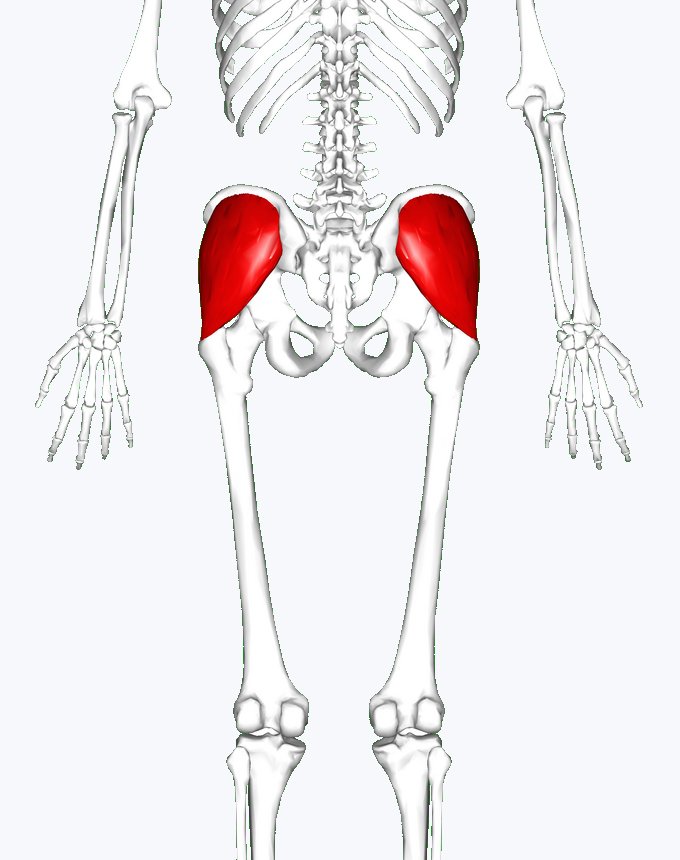
3D render of the pelvis from behind with both gluteus medius muscles highlighted in red
Gluteus medius, the main hip abductor. It works best when the femur is held in its normal adduction. Image: Anatomography, “Gluteus medius muscle01”, Wikimedia Commons, CC BY-SA 2.1 JP. Adapted: background changed, cropped.
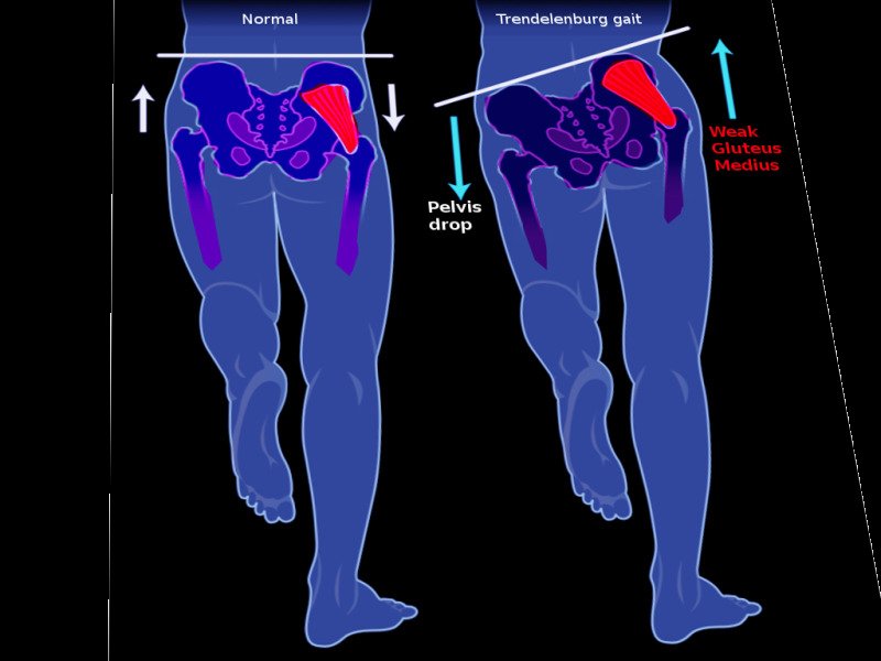
Diagram comparing a level pelvis with Trendelenburg gait, where the pelvis drops on the opposite side because of weak gluteus medius
Trendelenburg sign: when the stance-side abductors cannot hold the pelvis, it drops on the opposite (swing) side. Image: S. Bhimji, “Trendelenburg gait”, Wikimedia Commons, CC BY 4.0. Adapted: background filled.

Try it: coronal-plane model

GRF lever at the hip
Abductor demand

Simplified teaching model: demand is shown relative to a well-adducted femur (100%). Real values depend on body mass, limb length and socket fit.

Section 4

Knee stability: Radcliffe's equation

How much hip extension must the patient produce to stop the prosthetic knee buckling at loading response?

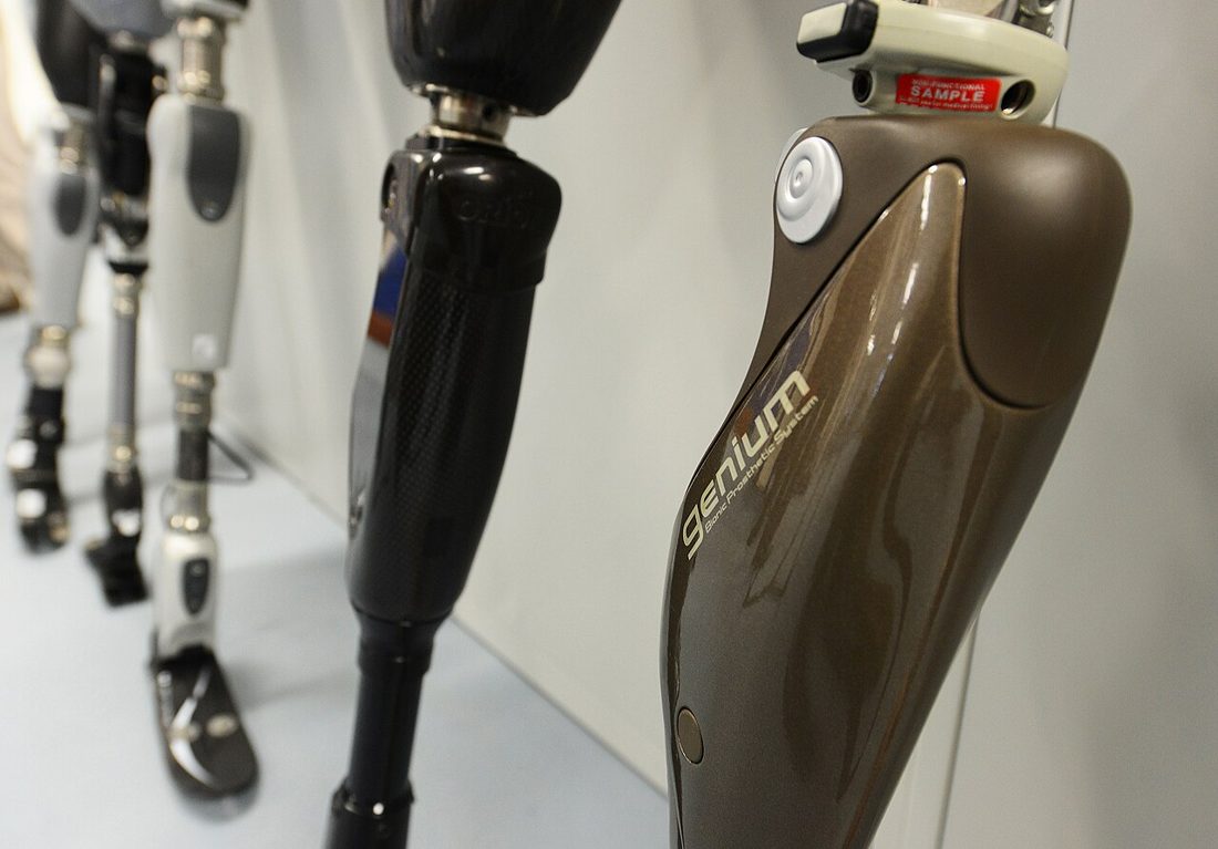
A row of prosthetic legs on display with microprocessor-controlled knees in the foreground
Microprocessor knees add controlled flexion resistance in stance: the Mk term below. The more resistance, the less hip effort is needed. Photo: Cpl Richard Cave RLC (Phot), “Prosthetic limbs at Headley Court”, UK MOD, Wikimedia Commons, Open Government Licence v1.0.

The equation

Mh = L (P·d − Mk) / h

Mh hip extensor moment needed · P axial load · d distance from knee axis to GRF (+ = GRF behind the knee) · Mk knee-unit flexion resistance · L hip to sole · h knee to sole.

Source: Radcliffe CW. Artificial Limbs 1955;2(1):35–60.

Try it: sagittal-plane model

Hip extensor moment Mh
Knee status

Start values match the in-class example (Khun B): P = 700 N, d = 0.05 m, L = 0.90 m, h = 0.50 m. Try Mk = 20, then try halving d.

Section 5

Shank length and swing timing

In swing the shank swings about the knee like a pendulum. In KD the prosthetic knee centre sits lower than the sound knee, so the shank is shorter and swings faster.

Stick-figure sequence of one gait cycle from initial contact to terminal swing
One gait cycle. In swing (right-hand figures) the shank must swing forward in time for the next initial contact. Image: chipotng, “Gait cycle by Jacquelin Perry”, Wikimedia Commons, CC BY-SA 3.0.

Try it: pendulum model

Sound period
Prosthetic period
Difference

Model: shank as a uniform rod swinging about the knee, T = 2π√(2A / 3g). Real swing also depends on the knee unit, mass and hip drive; the direction of the effect is what matters here.

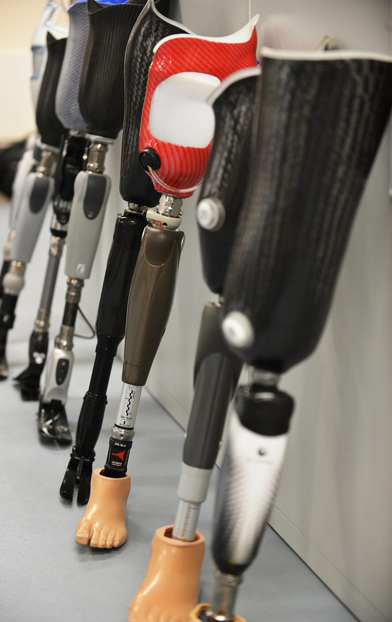
Several transfemoral prostheses with different knee units standing in a row
Knee units differ in build height. In KD, a compact or polycentric knee keeps the knee centre closer to the sound side. Photo: Cpl Richard Cave RLC (Phot), “Prosthetic limbs at Headley Court”, UK MOD, Wikimedia Commons, Open Government Licence v1.0.
Self-check

Ten-question quiz

Each answer shows an explanation. This does not count towards your grade.

Score: 0 / 10
Go further

Recommended reading

Start with the first two. Files are on Canvas.

Core

Transfemoral amputation: the basics and beyond

Clear overview of TF socket design, alignment and gait. Read the biomechanics chapters.

Berke GM, et al. Prosthetics Research Study, 2008.

Core

Knee control handout

Worked examples of the knee stability equation used in class.

Course handout (Canvas).

Classic

Functional considerations in the fitting of above-knee prostheses

The original source of the knee stability equation and the adducted-femur principle.

Radcliffe CW. Artificial Limbs 1955;2(1):35–60.

KD

Biomechanics of the through-knee prosthesis

Why end-bearing, the long lever and knee-centre height matter in KD.

Hughes J. Prosthet Orthot Int 1983;7(2):96–99.

Reference

Atlas of Amputations and Limb Deficiencies

Transfemoral prosthetic management chapter.

AAOS, 4th ed., 2016.

Evidence

Energy cost and falls

The sources for the energy-cost order and the falls figure in Section 1.

Waters RL, et al. J Bone Joint Surg Am 1976;58(1):42–46 · Miller WC, et al. Arch Phys Med Rehabil 2001;82(8):1031–1037.